
Boat hull: resistance study, Froude number and wave resistance
Studying the resistance of a boat hull means calculating the force that opposes its advance, in order to deduce the propulsive force needed at the chosen speed. This resistance to forward motion breaks down into viscous resistance, wave resistance and aerodynamic resistance. The Froude number, which compares the boat's speed with its waterline length, tells which wave system accompanies the hull and what it costs in resistance.
In this article:
- Hull resistance to forward motion: the three components
- Wave length and wave speed: the basic relation
- Froude number and wave resistance
- Interaction of bow and stern waves
- Wave regimes: Fn below 0.4, equal to 0.4, above 0.4 and above 0.5
- Method for calculating hull resistance, and the Heliciel tool

1: Hull resistance to forward motion: the three components
The resistance force, expressed in newtons, opposes the ship's course. We could measure it by towing the ship: the propulsion machinery must supply an equal and opposite force to hold the speed. But we cannot tow a ship that is not yet built. We therefore need a practical, accessible method that gives the designer and the shipbuilder concrete elements for sizing the propulsion machinery.
It is convenient to break the total hydrodynamic resistance (Rh) down into three main resistances:
- viscous resistance (Rv), made of the friction resistance, which depends on the wetted surface and its roughness, and the pressure resistance, which depends on the hull shape and the eddies it generates;
- wave resistance (Rw), which depends on the ship's speed and length;
- aerodynamic resistance (Ra) of the superstructures exposed to the wind, which we consider negligible here.
At low Froude numbers, viscous resistance accounts for 70 to 90% of the total resistance. To calculate it, we can use Heliciel following the tutorial on airship and submarine hull drag.
We owe to Froude this separate study of viscous, wave and aerodynamic resistance. The separation may seem questionable, because these forces interact: the wave forming along the hull changes the wetted surface, and therefore the friction resistance. But if we assess this interaction by distinguishing the different wave regimes, it offers calculation possibilities that give usable results for drawing hulls.
2: Wave length and wave speed: the basic relation
In deep water, a relation links the length L of a wave (distance between two crests, in metres) and its speed V (in m/s):
V / √(9.81 × L) = 0.4 that is L = (V / 0.4)² / 9.81 or L = (2π / 9.81) × V²
The factor 0.4 is rounded: it equals 1/√(2π), about 0.399.
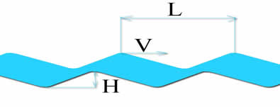
A wave of length L (between two crests) and height H, travelling at speed V.
Example: for a boat moving at 3 m/s, the length of the waves it produces is L = (2π / 9.81) × 3² = 0.640 × 9 ≈ 5.8 m.
Incidentally, the energy contained in a wave, per metre of crest width, is E (joules) = (1/8) × density (kg/m³) × 9.81 × H² × L. We could therefore estimate the energy absorbed by observed waves.
3: Froude number and wave resistance
The waves created by the ship travel at the same speed as it does. The relation L = (2π / 9.81) × V² therefore gives, with V replaced by the boat's speed, the distance between two crests of the waves it produces.
Replacing the wave length L in V / √(9.81 × L) by the waterline length Lf, Froude derived the number that accounts for wave effects on ship resistance: the Froude number.
Fn = C / √(9.81 × Lf)
with C the boat's speed (m/s) and Lf the waterline length (m). The Froude number Fn lets us assess the shape of the waves accompanying the ship. The figure below gives the wave regime and the specific resistance Rh/Δ (total hydrodynamic resistance divided by the displacement Δ = 9.81 × density × immersed volume) as a function of Fn, for several types of ship.
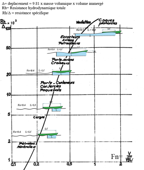
Specific resistance rises with the Froude number: tankers, cargo ships and container ships sail at low Fn; escorts, cruisers and then planing boats at ever higher Fn.
Let us look in detail at the remarkable values of the Froude number and their effect.
4: Interaction of bow and stern waves
Froude number below 0.4
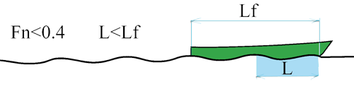
Fn below 0.4: the wave length L is smaller than the waterline length Lf, and several crests run along the hull.
At low Froude numbers (below 0.26), at least three low crests run along the boat. Wave resistance is small, and friction resistance accounts for 70 to 90% of the resistance to forward motion. Above 0.26, wave resistance increases, and the interaction between the bow wave and the stern wave plays a significant role, adding to or subtracting from the crest heights.
The ship mainly generates two wave trains:
- bow waves, which start at the bow;
- stern waves, created by the suction at the stern of the boat, which start at the stern and begin with a trough.
The position of the first crest of the bow wave depends on the Froude number, as the figure below shows.
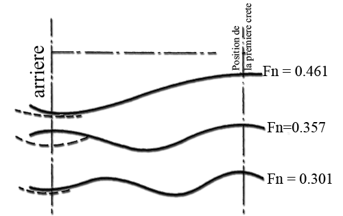
Wave profile for Fn = 0.461, 0.357 and 0.301: the higher Fn is, the longer the wave and the fewer crests along the hull.
We saw that wave energy grows with the square of its height H. We can therefore expect wave resistance to be stronger when the wave system generated by the hull has deep troughs. The adding or cancelling of bow and stern waves thus produces peaks and dips in wave resistance.
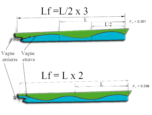
Two cases: Lf = 2 L (Fn = 0.266), where wave resistance passes through a minimum, and Lf = 3 × L/2 (Fn = 0.301), where it passes through a maximum.
- If Lf is a multiple of L, a crest of the bow wave overlaps and cancels the trough of the system born at the stern: the resistance to forward motion passes through a minimum.
- If Lf is an odd multiple of L/2 (for example Lf = L/2 or Lf = 3 × L/2), the bow wave shows a trough at the stern of the ship, which adds to the stern wave: the resistance to forward motion passes through a maximum.
These remarkable values correspond to a series of Froude numbers. We can place them, as a reminder, on a wave resistance curve:
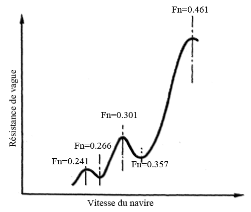
Wave resistance shows humps (Fn = 0.241, 0.301, 0.461) and dips (Fn = 0.266, 0.357) as speed increases.
5: Wave regimes: Fn below 0.4, equal to 0.4, above 0.4 and above 0.5
Froude number equal to 0.4
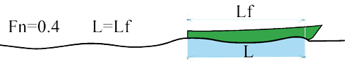
The wavelength matches the length of the hull, and the stern wave is cancelled by the bow wave. This is the theoretical limit speed for which the hull was designed. The ship sails in its own wave: a crest at the bow, a crest at the stern and the trough in the middle. Any further increase in speed is accompanied by a sharp rise in wave resistance.
Froude number above 0.4
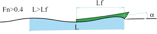
Between 0.4 and 0.5, the ship climbs onto its bow crest while the trough moves towards the stern. The hull tips and takes a trim: an angle appears. This is the worst situation and the most costly in wave resistance, which can reach 85% of the total resistance to forward motion. The ship presents a larger frontal area because of this angle. The resistance curve shoots up to a maximum at Fn = 0.461.
Froude number above 0.5
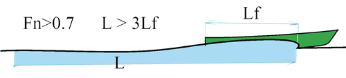
The ship rides on the crest of the bow wave, lifts its bow and returns to a horizontal position. This is the domain of planing hulls, which equip light vessels (the figure above corresponds to Fn above 0.7). A flat surface is provided at the stern to rest on the wave without sinking into it, and to keep as much of the hull as possible out of the water. Wave resistance falls sharply.
6: Method for calculating hull resistance, and the Heliciel tool
Consider calm, infinite water, and neglect aerodynamic resistance. The calculation method follows these steps:
- calculating the wetted surface;
- calculating the ship's displacement;
- calculating the Froude number;
- estimating the wave regime;
- estimating the ship's trim;
- estimating the residual drag, by Savitsky's method for a planing hull;
- calculating the viscous resistance: friction resistance and pressure (form) resistance.
This calculation chain is done in the Ship waves (Michell / Kelvin) window. Its Drag tab offers the generic ITTC method, the Holtrop & Mennen method for displacement hulls and the Savitsky method for planing hulls; wave resistance is calculated by Michell's theory. Details are on the page ship wave and drag study.
To go further, we can calculate the viscous resistance of an immersed body with the page on airship and submarine hull drag, then size the propeller that will supply this thrust with the boat propeller calculation.
 Global site map
 Mecaflux
 Tutorials Mecaflux Pro3D
 Tutorials Heliciel
 Tutorials Heliciel PRO CFD
 Mecaflux Store
 Compare software functions
 Quotes, Orders, Payment Methods
 project technical studies